Did you know that the wire drawing process can significantly enhance the mechanical properties of metals? According to industry studies, the wire drawing process can increase tensile strength and improve ductility, making it a pivotal step in the manufacturing chain. For manufacturers working with materials processed by CNC machining, understanding how to select an appropriate wire drawing method is essential to achieving optimal results.
to Wire Drawing and CNC Machining
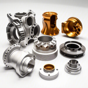
CNC (Computer Numerical Control) machining has revolutionized the manufacturing landscape by allowing precise and automated cutting of materials. However, it’s essential to realize that CNC machining is often just one part of the production process for components, especially in industries requiring high-strength alloys or specific mechanical properties like automotive and aerospace applications.
Once CNC machining is complete, the next step may often involve wire drawing. This manufacturing process stretches and reduces the diameter of metal rods or wires while enhancing their properties. But how do you determine which wire drawing process aligns with your CNC machined product’s requirements? This blog aims to explore that question in-depth.
Understanding Wire Drawing Processes
Wire drawing simplifies the material and shapes it into wires or rods through various techniques. Let’s break down some of the most common wire drawing processes:
Key Considerations for Selecting a Wire Drawing Process
Various factors can influence the choice of wire drawing process, including:

Tying Everything Together
To illustrate the considerations more effectively, let’s delve into a hypothetical case study. A company specializing in aerospace components decides to procure wires made from titanium alloy. After CNC machining, they are faced with choosing a wire drawing process.
This case study demonstrates how various factors converge to influence the decision-making process when selecting a wire drawing technique following CNC machining.
In the intricate world of metal manufacturing, understanding the wire drawing process after CNC machining is crucial for achieving optimal material performance. By considering factors such as material type, desired mechanical properties, wire diameter, production volume, costs, and post-processing requirements, manufacturers can confidently select the most appropriate wire drawing method.
Understanding these core technologies is not just about academic interest; it’s about making informed decisions that influence product quality and operational efficiency. As industries continue to evolve, the importance of effective manufacturing processes becomes ever clearer.
Considering the growing demands for more robust materials in applications ranging from aerospace to electronics, manufacturers would do well to incorporate a thorough understanding of post-CNC machining processes like wire drawing into their operational strategies. The right choice could ultimately be the difference between success and failure in the market.


-300x225.jpg)

-300x225.jpg)
